An explanation of some of Quicksilvers feature set
Stick Gestures
Quicksilver uses stick gestures for various functions. We use many inherited from Silverware plus some new ones.
Stick gestures are performed using just the Pitch/Roll stick and must be done side to side or up and down, not at an angle. They are fairly timing sensitive so for example gesture down,down,down should be performed about the same speed you'd say it out loud.
In these Docs gestures will be indicated by U,U,U or D,D,D etc.
| Stick Gesture | Action |
|---|---|
UP, UP, UP |
set bind flag |
DOWN, DOWN, DOWN |
save to flash, including bind. if no other gesture was performed, calibrate gyro |
RIGHT, RIGHT, RIGHT |
enter osd |
LEFT, RIGHT, LEFT |
re-draw osd, useful for hdzero |
Voltage
Quicksilver uses an algorithm which can be run on battery voltage while a pack is in use which estimates the resulting resting cell voltage if the quad were to land at that or any moment. We call this Fuel gauge volts.
It lets you know "how much gas is left in the tank"
Filtered voltage in contrast is just the exact voltage measured by the adc and then run through a filter to smooth it just a bit for human readability.
The Low Voltage warning feature is tied to fuel gauge voltage. So select a resting cell voltage you want to achieve after the end of a flight - update low voltage cutoff to that number.... fly until the warning is pretty consistently triggered (not just a brief flash) .... and when you land, the pack voltage will come to rest pretty close to your warning level.
Note: the low voltage warning (which will flash the lipo cell count upon trigger) is always tied to fuel gauge volts no matter which voltage data you choose to display.
So even while watching filtered voltage numbers - the cell count will still flash for low voltage based on fuel gauge volts.
The best source for moment to moment voltage telemetry or monitoring is filtered volts. This is hard coded for radio telemetry and is the default option for osd display.
For increased accuracy of the voltage features the voltage as measured by a multimeter or lipo tester of a fully charged lipo can be entered in the configurator along with the reported telemetry voltage from either the osd or your tx. Quicksilver will then calculate the correct actual value to use.
Filters
A Quick and Dirty Explanation
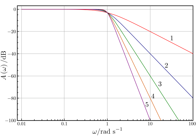
The Gyro filters Quicksilver uses are all lowpass filters this means they allow signal/noise below the specified frequency through. In quadcopters we are generally interested in frequencies under about 120Hz for gyro data, however the cutoff point is not a straight line and follows a slope. The steepness of this slope is indicated by the number after the "pt" part of a filter with pt1 being the shallowest angle and the angle increases in order.
The steeper the slope the stronger the filter but the greater the latency, ideally we want as little filtering and therefore latency as our build allows but enough to keep motors cool and flight smooth.
Filters chained eg. pass 1 and pass 2 will multiply the effect and increasing the order of filter increase noise attenuation but adds latency.
We have found that 2 passes of a pt1 filter generally needs a frequency of about 90HZ and increasing the order can sometimes mean only needing one pass at a frequency a bit higher eg. pt3 at 100Hz or 110Hz.
Dynamic D-term
Dynamic D term filter, a pt1 filter that moves up in cut frequency (Hz) with a parabolic relationship to applied throttle. The theory here is
that propwash is most likely to occur as throttle is applied in dirty air - and propwash is most significantly caused by latency in the D term filtering. Therefore, the approach is to reduce latency in the lowest frequency range of D term filtering which is responsible for the most phase delay as increasing throttle is applied. Noise pass-through will obviously increase with this approach, but when used in combination with "throttle_dterm_attenuation" gains on D will also be lowered with increasing throttle. This mitigates much of the danger from reduced filtering while allowing D term to be more effective at eliminating propwash.
Motor noise related to rpm is known to have a quadratic relationship with increasing throttle. While a quadratic curve could have been selected for this feature, a faster moving parabolic one was selected in its place as the goal is not to follow motor noise, but to get the filter out of the way as fast as possible in the interest of better performance and handling through reduced D filter latency when you need it most.
Dynamic Notch Filter
Add a dynamic notch filter pass to the gyro pipeline. A sdft algorithm is used to precisely track noise peaks in the gyro signal and then insert notch filters at these frequencies.
Throttle D-term attenuation (TDA)
Begins to reduce D-term above a set throttle percentage, TDA breakpoint to a maximum reduction, TDA percent
It works as a companion to the Dynamic D-term filter.
Throttle Boost
This adds high pass filtered throttle to the regular throttle, which will give more "sustained" power when making quick, throttle changing, inputs. It was pretty useful on brushed builds in acro, as those motors were a littler lazier to spool up and down.
It's not been tested very much with brushless motors.
This could affect your throttle management, but could be highly useful if you have a whoop thats a little lazy to pull out of maneuvers.
Suggested values are start with 0.1 and raise fairly slowly until you get the desired effect.
(We would appreciate feedback on this feature)
Torque Boost
Torque boost is a highly experimental feature and can smoke brushless motors fast. It is a low pass D term filter on motor outputs that will accelerate the response of the motors when the command to the motors is changing by increasing or decreasing the voltage thats sent.
It differs from throttle transient compensation in that it acts on all motor commands - not just throttle changes. this feature
is very noise sensitive so D term specifically has to be lowered and gyro/D filtering may need to be increased.
Recommendation right now is to keep boost at or below 2, drop your P gains a few points, then cut your D in half and
retune it back up to where it feels good. About 60 to 65% of your previous D value seems to work.
Stick Boost
GENERAL SUMMARY OF THIS FEATURE:
stickAccelerator and stickTransition are a more detailed version of the traditional D term setpoint weight and transition variables that you may be familiar with in other firmwares. The difference here is that we name the D term setpoint weight "Stick Accelerator" because it's actual function is to accelerate the response of the pid controller to stick inputs. Another difference is that negative stick transitions are possible meaning that you can have a higher stick acceleration near center stick which fades to a lower stick acceleration at full stick throws should you desire to see what that feels like. Traditionally we are only used to being able to transition from a low setpoint to a higher one. The final differences are that you can adjust each axis independently and also set up two seperate profiles so that you can switch "feels" in flight with the STICK_BOOST_PROFILE aux channel selection set up in the receiver section of config.h
HOW TO USE THIS FEATURE:
Safe values for stickAccelerator are from 0 to about 2.5 where 0 represents a "MEASUREMENT" based D term calculation and is the traditional Silverware PID controller, and a value of 1 represents an "ERROR" based D term calculation. Values above 1 add even more acceleration but be reasonable and keep this below about 2.5.
Range of acceptable values for stickTransition are from -1 to 1. Do not input a value outside of this range. When stick transition is 0 - no stick transition will take place and stick acceleration will remain constant regardless of stick position. Positive values up to 1 will represent a transition where stick acceleration at it's maximum at full stick deflection and is reduced by whatever percentage you enter here at stick center. For example accelerator at 1 and transition at .3 means that there will be 30% reduction of acceleration at stick center, and acceleration strength of 1 at full stick.
Angle Strength
Angle Strength adjusts how your craft responds to external forces from bumps to stick inputs Quicksilver has a "small error angle strength" and a "large error angle strength" - If you want to adjust your craft's "overreactions" to collisions - the intended path of user intervention is to reduce your "large error angle strength" Conversely, if you want your craft to feel more reactive in response to small stick movements - then this is where you adjust your "small error angle strength"
Receivers
Supported protocols:
- sbus (Frsky XM+ etc, Crossfire, Flysky)
- crsf (Crossfire/Tracer, ELRS)
- ibus (Flysky, Futaba)
- dsm2 (Spektrum)
- dsmx (Spektrum)
- SPI-ELRS
- SPI-Frsky
- SPI-Flysky
- SPI-Redpine
The correct protocol will be detected automatically as long as the uart the RX is soldered to is defined.
SPI connected RX will be detected if the SPI variant target has been flashed.
Firmware for SPI-RX is baked into Quicksilver depending on the board.
ExpressLRS passphrase use is encouraged.
LQ/RSSI
There are many ways to express what your radio link is doing, they all have limitations and depend on various environmental and hardware factors. What Quicksilver uses is packet rate as a percentage with 99 being maximum, no packets lost. ELRS users can select Direct from the LQI source dropdown for faster updates. This information lets you know how healthy your radio link is and can let you decide how much risk you want to take. Be aware that it can drop off very quickly once you are reaching the limit. A healthy radio link should remain in the 90-99 range.
Turtle mode
Turtle mode or flip over after crash works by detecting when the craft is inverted and then, when arm is activated it will follow Turtle mode logic. Input on the Pitch/Roll stick will cause the opposite direction motors to instantly spin to the value set in the Setup tab for 2 seconds. If this results in a successful flip over then a disarm, rearm will allow normal flight again.
For whoop style craft we recommend setting Turtle throttle to 100% Larger craft will need to have settings adjusted by 10% at a time to achieve a good result without stressing motors/esc too much, use caution! Turtle mode sttings are available in the OSD menu.
We also advise setting Turtle mode to ON in Receiver tab which means all you need do is arm while inverted and it's active.
OSD
The OSD menu is accessed by performing a R,R,R stick gesture on the ROLL/PITCH stick.
OSD font and boot logo can be changed, select and upload.
The OSD chip on the fc stores font and boot logo so if you want the Quicksilver boot logo you must upload a font once, it will then persist through future firmware flashes.
Each element can be positioned by altering the x,y numbers (0,0 is top left corner of the screen) and the font style can be inverted.
Callsign must be upper case only.
All OSD element settings are also available via the OSD menu. (stick gesture right,right,right) Most settings are available via the osd menu. Use the ROLL/PITCH stick to navigate the menus, RIGHT enters a category and LEFT exits out to the previous level. After making changes, SAVE+EXIT If changes are made and OSD is exited without SAVE+EXIT - changes will be temporarily applied but will not persist after battery disconnect. Some changes will cause a reboot after saving.
HDZero
Hdzero setup is easy as you only have to specify the uart that the vtx is connected to, everything else will be set. Left,right,left stick gesture redraws Quicksilver OSD after using the HDZero menus. If using HDZero it is important to power on the vrx before vtx. HDZero fonts are handled by the vrx or goggles and a custom Quicksilver HD font is available here
Blackbox
Two sample rates are available, 1000Hz capturing all fields and 200Hz capturing filtered gyro and time data for Gyroflow use. Files can be downloaded in .btfl format for use with PidToolbox and .quic format for use with the Guacalyzer, our own basic analyzer, available here
Motor Test
If selected via AUX or in OSD menu the motors will all spin on raising throttle when armed but will not be under PID control, use the pitch/roll stick to activate a single motor depending on stick position, in order to check the function of that motor. Very useful for checking for bent shafts quickly. This is not a flying mode and care must be taken to not spin motors too fast.
Runtime Targets
During the flashing process the target configuration for each flight controller is loaded after the firmware for the MCU. This is called the Runtime Target. The information is stored in a .yaml file format which is easily editable. This allows for adding target variations and potentially home brewed flight controllers. The Target files can be downloaded from the profile tab of the configurator and uploaded again with any changes.